.jpg)

.jpg)


%2Blarge%2Blug%2Bon%2Bthe%2Bneutral%2Bbus%2Bbar.%2BThe%2Bground%2Bwire%2B(bare%2Bcopper).jpg)


.jpg)


Updating Old House Wiring:
Adding A Sub-Panel - Part 3 -Installing And Wiring The New Panel
In This Article:
A new 125 Amp main lug panel is installed in a hole in the wall. The sub-feed cable is connected and new branch circuits are installed.
|
Related Articles:
|
Skill Level:
3+ (Intermediate or Higher)
|
Time Taken:
A Couple Of Hours
|
Start >>
A Basic Sub-Panel:

This is the Cutler-Hammer 125 Amp main lugelectrical panel.
There are two basic types of panels found at home centers: Main breaker and main lug.
Main breaker panels have a large breaker that disconnects the power to the hot bus bars. A main breaker panel is connected to a service entrance cable that leads into the house from the electric meter.
A main lug panel needs an external circuit breaker somewhere in the line feeding the panel. This could be a two-pole breaker in another breaker panel, or a circuit breaker in a disconnect box outside the house.
Identifying The Parts:
Ground Bus:
This row of screws is the ground bus. The ground wires are connected here.
The ground bus is typically fastened to the metal case of the breaker panel.

Neutral Bus:

This row of screws is one of two neutral bus bars.When this panel is used as a sub-panel, ONLY the neutral (white) wires are connected here.
Note the S-shaped piece of metal secured by a green screw. This is called a "bonding strap" and is used to connect (or "bond") the neutral bus to ground (the metal case) only when the panel is being used as a main panel.
If the bonding strap is used, the strap is inserted into one of the neutral terminal points, and the screws are tightened securely.
BUT WE CAN'T DO THIS... because we are using this panel as a subsidiary panel, or sub-panel. This panel is simply a branch of the main panel, and there is a strict rule about this neutral-and-ground connection:
The neutral and ground wires MUST be connected together, but ONLY at the main panel.

Why not connect the neutral and ground at other points in the system?
Because if a neutral wire became disconnected (I've seen it happen), the return path for electric current could be along a ground wire. While that itself may not be a big hazard, if that ground wire also became disconnected somewhere, parts of the ground system could be energized. That's not EVER supposed to happen.
The neutral wire is essentially a "low-risk" return path for the electric current in that branch of the system. All of the neutral wires all have the same electrical potential...nothing. At least, no potential compared to ground. There is, of course, 120 volts of potential difference between a neutral wire and any hot wire in the residential system.
If you touched the metal part of a live neutral wire you should not receive a shock. (But don't try it!) By tying the neutral to ground at one point, half of the conductors (in a typical 120 volt circuit) have no dangerous electrical potential. Of course, the hot wires are still dangerous.
Neutral Bus:

This large connector lug receives the neutral wire.
Hot Bus:
This is one of the two main lugs where the incoming hot wires connect to the hot bus bars.

Mounting The New Sub-Panel Box:

Arrow 1 points to one of four mounting hole knock-outs.
Arrow 2 points to a stamped guide line for flush mounting. In new construction, the panel would be installed with this line flush with the face of the studs, when using 1/2" thick drywall. The shorter line behind would be used with 5/8" drywall.
I used a nail set to punch out the mounting hole knock-outs.


We mounted the new sub-panel to the framing with 1-1/4" Simpson Strong-Drive screws.
But... we couldn't use the normal mounting holes. The plaster/lath and drywall multi-layer surface was so thick, the mounting screws would've just bit into plaster.
So we drilled four new holes farther back, so the screws would enter the wood framing.
We installed a 3/4" cable clamp in the bottom face of the panel. The sub-feed cable will pass through this clamp.


Sub-Feed:
We fished the 6-3G sub-feed cable through the large cable clamp.
Sub-Feed:
Below the sub-panel, I fastened the sub-feed cable to the framing with plastic cable straps and sheet metal screws.


Sub-Feed:
We tightened the screws on the cable clamp. Don't overdo this... the cable needs to be held firmly, not pinched in a death grip.
Sub-Feed:
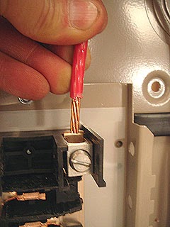
Inside the breaker panel, we carefully sliced through the cable jacket with a utility knife, and then cut off the jacket just above the clamp.


Sub-Feed:
The four wires inside the 6-3G sub-feed cable:
- Red and black, which are the hot wires.
- White, which is the neutral wire.
- Bare copper ground wire.
Connecting The Sub-Feed
To The Sub-Panel:
1. The hot wires (red and black) are connected to the hot bus bars.
2. The neutral (white) wire is connected to the large lug on the neutral bus bar.
3. The ground wire (bare copper) is connected to the ground bus.
The following photos show close-up views of these connections.

Some panel wiring suggestions:
It doesn't hurt to have a little extra wire inside the panel. When possible, I prefer to route the ground and neutral wires around the perimeter of the panel, in neat straight lines with corners. As the panel fills up, I will route the wires closer to the middle.

1. Connecting The Hot Wires:
These connectors need to be pretty tight... but I couldn't find a torque specification anywhere on the panel or in the instructions.
2. Connecting the Neutral Wire to the Large Lug:
This also needs to be quite tight.
The regular terminal points on the bus bar can accept wires from number 14 up to number 8. Larger wires (i.e. asmaller gauge number) require a larger lug.
Note that you can buy a large lug like this, which is installed in two terminal holes in the neutral bus bar.


3. Connecting the ground wire.
6-3G cable uses a smaller ground wire than the conductors (I think it's number 8), so the ground wire can fit into any of the connection points in the ground bus bar.
Adding Branch Circuits:
After punching out a knock-out and installing a cable clamp, we ran a piece of 14-2G non-metallic cable into the sub-panel.


The cable entered the panel from below, right next to the black sub-feed cable.
This circuit simply supplied power to a 2-gang junction box behind the sub-panel. From this point the circuit will feed a string of outlets and a ceiling fan.
Note that the cable must be secured to the framing within 12 inches of the panel. Also, the cable must be secured within 12 inches of the junction box.
Inside the sub-panel:
I carefully slit the cable jacket and cut away the plastic.


Inside the sub-panel:
I connected the ground wire to the ground bus.
To connect the white wire to the neutral bus, I made a sharp turn in the wire and stripped about 1/2" of insulation from the end.


The bare end of the wire goes under one of the screw terminals.
The screw needs to be fairly tight... about 30 to 50 inch-pounds I believe.
Installing A Cutler-Hammer Circuit Breaker:
The hot wire was connected to a 15 Amp single-pole breaker.


Now the breaker can be installed in the panel.
Before the breaker is installed, it's just dangling from the black (hot) wire.
Cutler-Hammer breakers have a hook on the back end...


... which grabs onto a metal flange in the circuit breaker panel.
The breaker pivots about the hook...


... and is pushed firmly in place onto the hot bus bar.
The first circuit breaker (red arrow) has been installed.
A rectangular knock-out needs to be removed from the cover panel to accommodate each breaker.

Related Electrical Articles:
Most Popular Electrical Articles:
Attention:
Before you hurt yourself, read our disclaimer.
HammerZone's Most Popular Pages:
- Installing Asphalt Roof Shingles
- How To Lay Out Stair Stringers
- How To Install A Circuit Breaker
- Installing A New Electrical Sub-Panel
- Frame A Rough Opening For A Window Or Door
- How To Replace A Toilet Wax Bowl Ring
Close Up:
How A Cutler-Hammer Circuit Breaker Connects To The Panel
The Cutler-Hammer circuit breaker uses a spring-loaded clamping mechanism to connect to the hot bus bar.


A Cutler-Hammer circuit breaker when seated fully against the hot bus bar:
Arrow 1 points to the connector prongs and the horseshoe-shaped spring.
Arrow 2 points to the hot bus bar. This is a sheet of heavy copper that has been folded over to form a wide tab that is grabbed by the breaker prongs.
Recommended Reading:
I highly recommend the book Wiring a House (For Pros By Pros) by Rex Cauldwell, which is available on Amazon.com.
Warnings And Cautions:
I strongly recommend anybody who plans on doing their own electrical work to do more research besides just reading these articles. I am not an electrician and I certainly do not know everything about wiring. I could be wrong. The electrical codes in your area may be different than in my area.
While minor electrical changes and repairs may not require a permit, larger projects usually do. Consult your local Building Department (look in the "local government" section of your phone book) before making your own major electrical changes. Local electrical inspectors usually are available during their early morning hours to answer your code questions, normally free of charge. If you've done your homework, you can speak intelligently and learn about lots of valuable rules and regulations.
No comments:
Post a Comment