 | Old House Wiring:
Replacing Old, Worn-Out
Electrical Outlets
|
| In This Article:After the power is shut off, worn out electrical outlets are removed and replaced, and ground wire connections are corrected. | Related Articles:
|
| Skill Level: 2 (Basic) | Time Taken: Half An Hour |
Electrical outlets wear out. A new outlet will hold a plug quite firmly, but after years of use the outlet will lose its grip. It's common to find 20 or 30 year old outlets that are so loose that a cord barely stays in place. This isn't just a nuisance, this is a hazard. Loose-fitting plugs canarc, which is essentially small-scale lightning. Arcing will create heat, and if the arcing is bad enough the heat can melt the surrounding wiring and start a fire. I've seen it happen.
 | All of the outlets (officially known as receptacles) in this 40-year-old house were candidates for replacement.While many were simply worn out, I don't care for the contemporary look of white outlets and switches.
Some people change their electrical devices simply for color preferences. |
|
| Sometimes previous owners have painted over the outlets. It's easier to replace an outlet than to try to scrape off the paint. |  |
|
 | This outlet was among the worst in the house... it was loose, the plastic was cracked, and it was painted over. |
|
But First...
Turn Off The Power!
I turned off the circuit breaker that supplied the room I was working on.
Using a non-contact voltage tester, I double-checkedthat the power was off.
Don't assume that all outlets in one room are on the same circuit... I have one outlet in the living room that is part of a kitchen circuit. |  |
|
 | I removed the outlet mounting screws.I used a cordless drill instead of a slot screwdriver, since I was replacing a couple dozen outlets. |
|
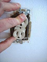
| The old outlet had been painted over, so I carefully pried the metal tabs away from the wallboard.This is one spot where I don't want the drywall to break. |  |
|
 | I pulled the outlet straight out from the metal junction box. |
|
| I unscrewed the connector screws. Since I'm throwing away these old outlets, I completely removed the screws. |  |
|
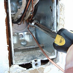
 | This screw on the hot side had evidence of a short circuit. Notice the black soot marks and melted metal (red arrow). |
|
| Right beside it, on the metal junction box, there was a corresponding black soot mark. |  |
|
This is typical evidence of a short circuit sometime in the past. Somebody probably stuck a metal object into the side of the junction box when the cover plate was removed. Simply wrapping the outlet in electrical tape can prevent this.
 | Once the device was removed, I pulled the wires from the J-box. |
|
| The ground wires had been twisted together, but not connected to the outlet.In some of the J-boxes the ground wires had been wrapped under a screw head. In this case there was no attempt to fasten the wire to the box. |  |
|
 | Using a pair of pliers I pulled the ground wires so they stuck out. |
|
I consider myself lucky to have ground wires like these.This house was built in 1962-63, and around that time grounded wiring was becoming a requirement. I've seen newer houses where non-grounded wiring was used, or worse, where somebody had clipped off the ground wires deep in the junction box.
I've also seen houses from this era where grounded wiring was used and the ground wire was not connected but carefully wrapped around the cable where it entered the junction box, to be connected at a later date. |
|
Connecting The Ground Wires Properly:
In some of the junction boxes one ground wire was wrapped around a screw that secured the cables in place. In other boxes, the ground wire was not connected to anything. Current electrical codes require a metal junction box to have a ground wire securely attached, either using a ground screw or an approved fastener.
| Using needle-nose pliers, I made a shepherd's hook on the end of a 4-inch piece of ground wire. |  |
|
 | This is a ground screw. I bought a pack of 100 for about 6 bucks at Home Depot. |
|
| I put the screw in the hook and pinched it with pliers.Then I bent the wire into an "L" shape. |  |
|
 | In the back of the metal J-box there were two holes. Luckily the ground screw (which has an 8-32 thread) fit into these holes. |
|
| Using a 5/16" nut driver, I fastened the ground wire "pig-tail" to the hole in the box. |  |
|
 | Using lineman's pliers, I untwisted the original ground wires.I've never found it easy to add another wire to a group of already-twisted wires. |
|
| I placed the box ground pig-tail next to the original grounds, and I also placed another pig-tail next to those. |  |
|
 | While holding the cluster of ground wires with one hand, I used the lineman's pliers to twist the four bare wires into a solid-feeling connection. |
|
| I clipped off ends so they would all be the same length. |  |
|
 | I installed a red twist-on wire connector (commonly called a "wire nut") to hold the wires together.A yellow wire nut might have barely fit (since the old ground wires are very small... they look like number 16 wire), but I used the larger red connector. |
|
| I pushed the cluster of ground wires into the back of the J-box.I try to keep the wires neatly folded so I'll have adequate room in these old junction boxes. |  |
|
Connecting The New Outlet:
 | I made a hook on the other end of that fourth ground wire. |
|
| I hooked the ground wire over the green terminal on the new outlet. |  |
|
 | I pinched the hook almost closed. This may not be necessary, but I do it to ensure that the wire stays where I want it, even if the screw gets loose. |
|
| I tightened the ground screw firmly. |  |
|
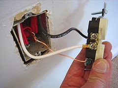
| I connected the white (neutral) wires to the silver screws. |
|
Note that there are two white wires and two black wires. One cable (consisting of a black, white, and bare ground wire) is feeding the box with power, and the other cable feeds another box downstream somewhere.
In this case the white wires are connected together AND connected to the outlet. Since the outlet has two screws, it's common practice to simply connect the incoming white wire to one silver screw, and the outgoing white wire to the other screw. The black wires are treated similarly.
| I connected the black (hot) wires to the gold screws. |  |
|
Another method of wiring is to use a wire nut to connect the incoming and outgoing wires, and a short pigtail wire which connects to the outlet.
 | I wrapped electrical tape around the sides of the outlet, making sure there were two layers over the gold screws. |
|
| To push the outlet back into the box, I made sure the wires made an "accordion" or "W" shape. |  |
|
My Trick For Pushing Outlets Into A J-Box:
 | First I tilted the outlet and pushed it into the box on an angle.Note that the screws are going on the outside of this metal J-box. |
|
| Then I pulled the outlet back out, rotated it the other way, and pushed it into the box again.This seems to force the wires to fold properly in the box. |  |
|
I again pulled the outlet from the J-box, and then I pushed it back with the screws aligned with the mounting holes.
This process takes a few extra seconds, but seems to be worth the effort, especially with number 12 wire and larger.
 | I screwed the outlet to the junction box. |
|
| Finished job: A new outlet. |  |
|
 | Since I'm going to be repainting the room, I covered the outlet with 2-inch blue masking tape. |
|
More Outlets:
A Problem:
This outlet had three wires that combined into one wire... and the connection was wrapped in electrical tape. |  |
|
 | I removed the electrical tape to reveal a pair of soldered connections (red arrows).This method was done a l-o-n-g time ago. Soldering wire connections is a really sturdy method, if the wires are twisted together properly. But... it's too time-consuming, and it can't be undone easily. |
|
| These are Ideal® Term-a-Nut® wire connectors. These allow 2 to 4 number 12 wires to be joined together and have a pig-tail for connecting to an outlet.These are great for extending the reach of a group of wires that barely protrude from a junction box. |  |
|
 | I cut the wires just upstream of the soldered connection, stripped the ends, and attached the Term-a-Nut by twisting it on the ends of the wires. |
|
| Then I connected the Term-a-Nut to the outlet. |  |
|
Another Grounding Method:
 | I made a bare pig-tail about 8 inches long, and used a green ground screw to connect it to the J-box. |
|
| Using a pair of pliers I twisted the old ground wires and the new pig-tail. |  |
|
 | I slipped a green wire nut over the long bare wire, and twisted it onto the connection.Then I made the shepherd's hook and connected the ground wire to the outlet as usual.
An electrical inspector once told me that the shortest ground wires need to extend at least 3 inches from the box, and the longest ground needs to extend at least 6 inches outside the box. |
|
Tools Used:
- Cordless Drill/Driver
- Phillips Screwdriver
- Needle-nose Pliers
- Lineman's Pliers
- Wire Strippers
| Materials Used:
- Duplex Receptacle (Outlet)
- Wire Nuts
- Ideal® Term-A-Nut® Wire Connectors
- Electrical Tape
|


No comments:
Post a Comment